Schematic Objects 555 IC

Chapter 10.2

Down For The Count


Introduction
Chapter 1 - Electricity
Chapter 1.2 - The Numbers

Chapter 2 – Sharing and Bonding

Chapter 3 - Voltage
Chapter 3.2 – Voltage Static
Chapter 3.3 - Batteries
Chapter 3.4 – Solar - Others

Chapter 4 - Resistance
Chapter 4.2 – Parallel Resistance
Chapter 4.3 – Voltage Dividers

Chapter 5 - Semiconductor
Chapter 5.2 - PNP NPN Junctions

Chapter 6 – AC and Hertz

Chapter 7 - Magnetism
Chapter 7.2 - Inductors

Chapter 8 - Capacitor

Chapter 9 - IC's and OP-AMP's
Chapter 9.2 - Feedback, Unity Gain
Chapter 9.3 - Non-inverting Amplifier
Chapter 9.4 - Inverting Amplifier

Chapter 10 - 555 Timer
Chapter 10.2 - 555 Timer- Part 2

Chapter 11 - Logic

Chapter 12 - The Power Supply
Chapter 12.2 - More on Power Supplies

555 As A Monostable Mulivibrator

P-N Junction 
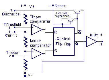
This configuration of the 555 is called a ONE-SHOT Mulivibrator. The name comes from the circuit configuration allowing one action after the trigger. Once triggered, the output will stay in the triggered state for a period of time based on the RC time interval. Then switch back to the wait state and wait until another trigger is sent. NOTE: As we move on in the study other oscillator circuits using different components will also be referred to as a ONE-SHOT Mulivibrator.

This schematic is very similar to the prior one. A Switch S1 has been added to trigger the circuit. Here is how it works.

At first powered on, the output (pin 3) is 1 or on, and
   the LED is lit.  
 R2 is holding the trigger (pin 2) high, causing the flip-flop S
   to be state 0.  C1 is discharged and starts to charge through
   R1. NOTE: C1 is considered discharges at the beginning.
 
 When C1 is charged to 2/3 supply voltage the upper comparators 
   non-inverting input will cause it to switch setting the flip-flop
   R to state 1.  At that moment the flip-flop will switch output
   states, Q will be 0, and the LED goes dark.  There is more going
   on though. The discharge circuit will discharge C1, the upper
   comparator will switch back to its output state 0 setting and
   the flop-flop R to state 0.

 Now the circuit will wait for a trigger. Until the battery runs
   down if need be.

 There are three ways to look at the trigger.
  1) Press and never releasing the trigger, the led will stay on.
       No real value in the fancy circuitry here.
  2) Press and hold the trigger longer then the RC interval the LED
       will be on while triggered and shut off when it is released.
       No real value in the fancy circuitry here either.
  3) Press and immediately released the trigger and the LED will
       stay lit for the RC time interval. 

 What are the parts in the circuit?
   555 is the IC
   R1 is the circuit timing resistor
   R2 is a Pin 2 pull-up resistor for a logical high state.
   R3 limits LED current
   C1 is the circuit timing capacitor
   S1 is the trigger.
   One shot has only one time cycle, T = 1.1 (R1 x C1)

Experiment - Monostable Mulivibrator and an LED:

Go to the work bench. Review the Resistor Color Code chart and wire up the kit as described. Perform the lab, and record your results.

P-N Junction
Parts List:
  1 9-volt battery
  1 Battery power clip
  1 555 IC - U1
  1 10 mmf capacitor - C1
  1 1 k ohm resistor - R3
      (brown, black, red)
  2 100 k ohm resistor - R1, R2
      (brown, black, yellow)
  1 red light emitting diode
  1 experimenters board
  Miscellaneous:
    hookup wire
P-N Junction

NOTES: The flat side of the LED is toward the V- side of the circuit. The minus side of the C1 capacitor is toward the V- side of the circuit.


« Previous Next Chapter »
Copyright 2007-2012, All Right Reserved