Schematic Objects Coil

Chapter 7.2

Transforming Electricity - Introduction


Introduction
Chapter 1 - Electricity
Chapter 1.2 - The Numbers

Chapter 2 – Sharing and Bonding

Chapter 3 - Voltage
Chapter 3.2 – Voltage Static
Chapter 3.3 - Batteries
Chapter 3.4 – Solar - Others

Chapter 4 - Resistance
Chapter 4.2 – Parallel Resistance
Chapter 4.3 – Voltage Dividers

Chapter 5 - Semiconductor
Chapter 5.2 - PNP NPN Junctions

Chapter 6 – AC and Hertz

Chapter 7 - Magnetism
Chapter 7.2 - Inductors

Chapter 8 - Capacitor

Chapter 9 - IC's and Amplifier

Chapter 10 - 555 Timer

Chapter 11 - Logic

Chapter 12 - Power Supply

Inductors In Series

Series Inductors 
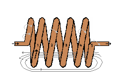
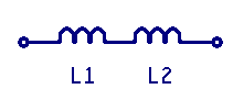
When inductors are in series in a circuit, the current will flow equally through the series of inductors. The total inductance for the series is calculated by adding the values of all series inductors together. This is similar to way that series resistors are calculated. The formula for inductor in series is L-equivalent = L1 + L2. If L1 equals 3 millihenrys and L2 equals 2 millihenrys the total is 5 millihenrys.
Parallel Inductors

Inductors In Parallel

Similar formulas are used for Inductors wired in a circuit when they are parallel as resistors use when they are in parallel. For indictors in parallel this is similar to calculating resistors in parallel.
L-equivalent=   ( 1 / ( ( 1/L1 )+( 1/L2 ) ) )   
If L1 equals 3 mH and L2 equals 2 mH the total is 1.2 millihenrys.

Other factors that affect the inductance.

1. Core material: Some core materials including Iron are more able to support flux lines over materials like open air cores. This ability to support flux lines means iron cores will have more inductance and air cores will have less inductance.
2. Diameter of core: The larger the diameter of the cores cross-sectional area the more lines of force exist and the greater the inductance. Even if the turns count remains the same, increased core diameter will increase the conductor linear surface area and this will increase the inductance.
3. Increased turns: Increasing the turns in the core will increase the inductance.
4. Tightly wrapped coil. The tighter the coil is wrapped the more inductance will be created.

Inductive Reactance (XL)

Both resistance and the change in flux lines in inductance are in oppositions to current flow.
In a pure resistance circuit, the resistance to current flow, in Ohms, is the same in both direct current (DC) and alternating current (AC) circuits.
This is not the same for inductance. The Ohms of resistance for inductors in a circuit is directly proportional to the AC frequency of the waveform in that circuit.

This AC resistance uses the special name of Impedance. Like resistance, Impedance opposes the flow of current. For any given inductance value, the inductor blocks more current flow and passes less energy as the frequency increases. As with all electronics there is a formula that represents this reaction to frequencies.

 Inductive Reactance (XL) formula is XL = 2 Π f L
          In short Inductive Reactance is the impedance (AC Resistance)
          of an inductor at a specific frequency.  

 Where:	XL is the AC resistance to current flow
        2 Π is a constant of 2(3.14159)
        f is the frequency of the voltage in Hz
        L is the inductance of the coil in Henrys

  Example: Given a 10mH coil of wire, apply three different frequencies
           and record the three different impedance calculations.
 
  The inductance is 10mH  (0.010 Henrys)
  The frequencies are 60 Hz, 400 Hz and 1kHz
  The formals are: XL = 2 Π  f L
	For  60 Hz - XL = (2)(3.14159)(60)(0.010) or XL = 3.77  Ω 
        For 400 Hz - XL = (2)(3.14159)(400)(0.010) or XL = 25.13  Ω
        For  1k Hz - XL = (2)(3.14159)(1000)(0.010) or  XL = 62.83  Ω

  As the frequency moved from 60Hz to 1KHz the AC resistance
     increases from 3.77 to 62.83 Ohms.

  Example: Given a 1 Henry coil, and the same three frequencies
           record the three different impedance calculations.

        For  60 Hz - XL = (2)(3.14159)(60)(1) or XL = 377  Ω
        For 400 Hz - XL = (2)(3.14159)(400)(1) or XL = 2.5 k Ω
        For  1k Hz - XL = (2)(3.14159)(1000)(1) or  XL = 6.28 k Ω

There are other factures that we are not considering at this time including the amount of current the coil can carry. In summery a conductor which is passing by a magnetic flux field, will generate a voltage, and within a circuit, current will flow. Conversely when current flows through a conductor an electromagnetic field (magnetic flux) is created. If two or more independent coils of wire are placed in close proximately to each other and one coil has a varying current flowing through it, it will induce a current to flow in the other coil(s) in circuit(s). The multi-coil arrangement is called a transformer. The principle of transferring energy into the second coil is called induction. In inductors, the Ohms resistance to a change in current flow is called impedance. The inductors impedance increases proportionately with frequency. The inductors impedance increases proportionately with its increase in inductance.
In the next section we will study the complementary component to an inductor, which is a capacitor. A capacitor stores its energy on it plates.


« Previous Next Chapter »
Copyright 2007-2012, All Right Reserved