Introduction
Chapter 1 - Electricity
Chapter 1.2 - The Numbers
Chapter 2 ľ Sharing and Bonding
Chapter 3 - Voltage
Chapter 3.2 ľ Voltage Static
Chapter 3.3 - Batteries
Chapter 3.4 ľ Solar - Others
Chapter 4 - Resistance
Chapter 4.2 ľ Parallel Resistance
Chapter 4.3 ľ Voltage Dividers
Chapter 5 - Semiconductor
Chapter 5.2 - PNP NPN Junctions
Chapter 6 ľ AC and Hertz
Chapter 7 - Magnetism
Chapter 7.2 - Inductors
Chapter 8 - Capacitor
Chapter 9 - IC's and OP-AMP's
Chapter 9.2 - Feedback, Unity Gain
Chapter 9.3 - Non-inverting Amplifier
Chapter 9.4 - Inverting Amplifier
Chapter 10 - 555 Timer
Chapter 10.2 - 555 Timer- Part 2
Chapter 11 - Logic
Chapter 12 - The Power Supply
Chapter 12.2 - More on Power Supplies
|
|
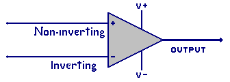
 These are schematic symbols for the Op Amp. The first is without the power supply
leads drawn in. Sometimes the power supply leads are not shown in the drawings.
The second graphic shows the power supply pins-outs (leads).
These are schematic symbols for the Op Amp. The first is without the power supply
leads drawn in. Sometimes the power supply leads are not shown in the drawings.
The second graphic shows the power supply pins-outs (leads).
 Additionally,
some amplifiers can provide higher output power, higher frequencies, wider
operating temperatures, faster switching speeds, and more functions.
This is why there is no general Op Amp type or case size.
Looking at the second graphic, there are at lease 5 connections to consider in any
general Op Amp. There are two power connections, for the V+ and V- power supply.
There are two input connections for non-inverting (+) and inverting (-) inputs.
These is one output connection.
Additionally,
some amplifiers can provide higher output power, higher frequencies, wider
operating temperatures, faster switching speeds, and more functions.
This is why there is no general Op Amp type or case size.
Looking at the second graphic, there are at lease 5 connections to consider in any
general Op Amp. There are two power connections, for the V+ and V- power supply.
There are two input connections for non-inverting (+) and inverting (-) inputs.
These is one output connection.
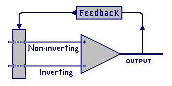 b) The output voltage is fed
back to the input.
c) Op Amp inputs are the sums
of all input source voltages
plus all feedback voltages.
d) Negative feedback is the
feedback applied to the
inverting input.
e) Positive feedback is applied
to the non-inverting input
f) Without feedback the Op Amp works as a switch
2) The Op Amp is a voltage amplifier with the capability to provide
a very high voltage gain.
3) The Op Amp has a range of acceptable operating power supply
voltages that it must stay within.
4) The input voltage must not exceed the power supply voltage.
a) It can not be higher(more) then the V+ supply voltage
b) It can not be lower (less) then the V- supply voltage
5) The inputs do not draw current. (in theory )
6) As a comparator the Op Amp will compare the inverting and
non-inverting inputs. When the non-inverting is more
positive then the inverting the output voltage will be near
V+. If the inverting is more positive the output will near
the V-.
Remember that these are general Rules!
b) The output voltage is fed
back to the input.
c) Op Amp inputs are the sums
of all input source voltages
plus all feedback voltages.
d) Negative feedback is the
feedback applied to the
inverting input.
e) Positive feedback is applied
to the non-inverting input
f) Without feedback the Op Amp works as a switch
2) The Op Amp is a voltage amplifier with the capability to provide
a very high voltage gain.
3) The Op Amp has a range of acceptable operating power supply
voltages that it must stay within.
4) The input voltage must not exceed the power supply voltage.
a) It can not be higher(more) then the V+ supply voltage
b) It can not be lower (less) then the V- supply voltage
5) The inputs do not draw current. (in theory )
6) As a comparator the Op Amp will compare the inverting and
non-inverting inputs. When the non-inverting is more
positive then the inverting the output voltage will be near
V+. If the inverting is more positive the output will near
the V-.
Remember that these are general Rules!
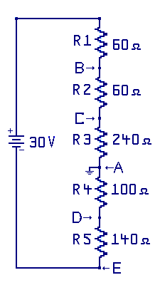 Here is a graphic from an earlier section on voltage dividers. This same
technique will be used for providing simple voltage sources, and used for a
simple feedback network.
Here is a graphic from an earlier section on voltage dividers. This same
technique will be used for providing simple voltage sources, and used for a
simple feedback network.