Chapter 4.2
Resistance
Introduction
Chapter 1 - Electricity
Chapter 1.2 - The Numbers
Chapter 2 – Sharing and Bonding
Chapter 3 - Voltage
Chapter 3.2 – Voltage Static
Chapter 3.3 - Batteries
Chapter 3.4 – Solar - Others
Chapter 4 - Resistance
Chapter 4.2 – Parallel Resistance
Chapter 4.3 – Voltage Dividers
Chapter 5 - Semiconductor
Chapter 5.2 - PNP NPN Junctions
Chapter 6 – AC and Hertz
Chapter 7 - Magnetism
Chapter 7.2 - Inductors
Chapter 8 - Capacitor
Chapter 9 - IC's and Amplifier
Chapter 10 - 555 Timer
Chapter 11 - Logic
Chapter 12 - Power Supply
|
|
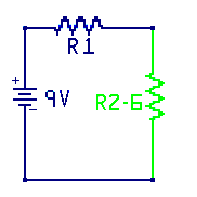
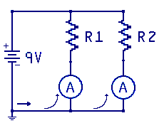 In this circuit diagram there are two resistors labeled R1 and R2 wired
in parallel. Some of the current will flow through R1
and some other current will flow through R2. One question that comes to mind
is how much current flows through each path? The voltage across each resistor is the same.
In this circuit diagram there are two resistors labeled R1 and R2 wired
in parallel. Some of the current will flow through R1
and some other current will flow through R2. One question that comes to mind
is how much current flows through each path? The voltage across each resistor is the same.
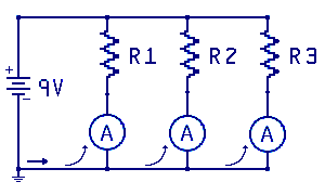 In this circuit diagram three resistors labeled R1, R2 and R3 wired
in parallel. In this circuit the current is split into three paths.
In this circuit diagram three resistors labeled R1, R2 and R3 wired
in parallel. In this circuit the current is split into three paths.
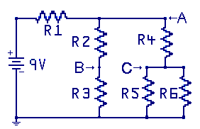
 Solve the parallel set R5 and R6
Work: R56 = (1000x1000) / (1000 + 1000) = 500 Ohms
R-equivalent R56 = 500 Ohms
After redrawing the circuit with the new R56
resistor in place, it should look like this.
Step 2:
Solve the parallel set R5 and R6
Work: R56 = (1000x1000) / (1000 + 1000) = 500 Ohms
R-equivalent R56 = 500 Ohms
After redrawing the circuit with the new R56
resistor in place, it should look like this.
Step 2:
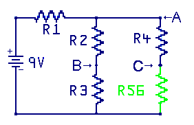
 Solve the series set R4 and R56
Work R456 = 1000 + 500 = 1500 Ohms
R-equivalent R456 = 1500 Ohms
After redrawing the circuit with the new R456
resistor in place, it should look like this.
Step 3:
Solve the series set R4 and R56
Work R456 = 1000 + 500 = 1500 Ohms
R-equivalent R456 = 1500 Ohms
After redrawing the circuit with the new R456
resistor in place, it should look like this.
Step 3:
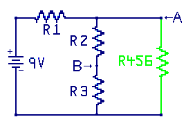
 Solve the series set R2 and R3
Work R23 = 1000 + 1000 = 2k Ohms
R-equivalent R23 = 2k Ohms
After redrawing the circuit with the new R23
resistor in place, it should look like this.
Step 4:
Solve the series set R2 and R3
Work R23 = 1000 + 1000 = 2k Ohms
R-equivalent R23 = 2k Ohms
After redrawing the circuit with the new R23
resistor in place, it should look like this.
Step 4:
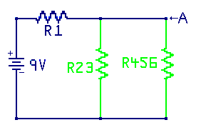
 Solve the parallel set R23 and R456
Work R2-6 ( 1500 x 2000 ) / (1500 + 2000 ) = 857 ohms
R-equivalent R2-6 = 857 Ohms
After redrawing the circuit with the new R2to6
resistor in place, it should look like this.
Step 5: Solve the series set R1 and R2-6 and this
is the real R-equivalent across the source power supply.
Work: Total R = 1000 + 857 = 1857 Ohms
Step 6: Find the total circuit current.
Work: Current = 9 V / 1857 R = 4.85 mA
Step 7: Find the voltage at point A with respect to the battery
minus terminal (-)
Work: Supply voltage minus R1 voltage drop.
9V – ( 1000 X 0.00485) = 4.15 V
Step 8: Find the voltage at point B with respect to the battery
minus terminal (-)
Known: Voltage at point A is 4.15 volts.
R23 is a voltage divider across the 4.15 volts.
Voltage at point B is half voltage at point A or 2.075 volts
Step 9: Find the voltage at point C with respect to the battery
minus terminal (-)
Known: Voltage at point A = 4.15
R4 and R56 is voltage divider across the 4.15 volts.
R56 is one third the resistance of the divider.
Voltage at point C = 4.15(V) times .33 = 1.39 V
Option 2: Using R456 and voltage A,
calculate current through R456, then voltage across R56
Solve the parallel set R23 and R456
Work R2-6 ( 1500 x 2000 ) / (1500 + 2000 ) = 857 ohms
R-equivalent R2-6 = 857 Ohms
After redrawing the circuit with the new R2to6
resistor in place, it should look like this.
Step 5: Solve the series set R1 and R2-6 and this
is the real R-equivalent across the source power supply.
Work: Total R = 1000 + 857 = 1857 Ohms
Step 6: Find the total circuit current.
Work: Current = 9 V / 1857 R = 4.85 mA
Step 7: Find the voltage at point A with respect to the battery
minus terminal (-)
Work: Supply voltage minus R1 voltage drop.
9V – ( 1000 X 0.00485) = 4.15 V
Step 8: Find the voltage at point B with respect to the battery
minus terminal (-)
Known: Voltage at point A is 4.15 volts.
R23 is a voltage divider across the 4.15 volts.
Voltage at point B is half voltage at point A or 2.075 volts
Step 9: Find the voltage at point C with respect to the battery
minus terminal (-)
Known: Voltage at point A = 4.15
R4 and R56 is voltage divider across the 4.15 volts.
R56 is one third the resistance of the divider.
Voltage at point C = 4.15(V) times .33 = 1.39 V
Option 2: Using R456 and voltage A,
calculate current through R456, then voltage across R56