Schematic Objects Halfwave supply logic

Chapter 12.2

The Power Supply.


Introduction
Chapter 1 - Electricity

Chapter 2 – Sharing and Bonding

Chapter 3 - Voltage

Chapter 4 - Resistance

Chapter 5 - Semiconductor

Chapter 6 – AC and Hertz

Chapter 7 - Magnetism
Chapter 7.2 - Inductors

Chapter 8 - Capacitor

Chapter 9 - IC's and OP-AMP's
Chapter 9.2 - Feedback, Unity Gain
Chapter 9.3 - Non-inverting Amplifier
Chapter 9.4 - Inverting Amplifier

Chapter 10 - 555 Timer
Chapter 10.2 - 555 Timer- Part 2

Chapter 11 - Logic

Chapter 12 - The Power Supply
Chapter 12.2 - More on Power Supplies

Filtering the power

Capacitor Filter 
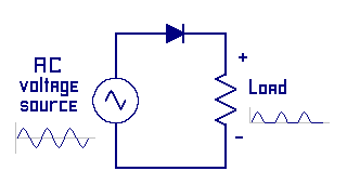
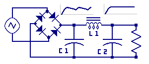
Look at this circuit. We are bringing many components together to build this power supply. Starting on the left side we see the symbol for an alternating current source. Remember that this is a general symbol representing an AC voltage from any source. These, might include power from a wall outlet, wind generator, from the secondary coil of a transformer, or from test equipment called a signal generator.

BRIDGE RECTIFIER: The AC source is applied to the bridge rectifier which converts the voltage to DC. Recall this diode arrangement converts both half’s of the AC wave form into a DC output.

CAPACITOR C1: Next recall from the section on the capacitor that this C1 can store energy on its plates when the surrounding voltage is higher then the plate voltage. C1 release voltage back into the circuit when the plate voltage is higher then the circuit voltage. Another characteristic is that the bridge rectifier is such a powerful source to C1, that C1 changes nearly instantaneously from the supply. Next, providing the load on the power supply is sized correctly the capacitor will be able to provide voltage back into the circuit without being drained much before the next boost of power comes from the rectifier. In this illustration C1, called a filter capacitor, is filtering or removing some of the ripple from the rectifier voltage through its ability to store and return energy.

INDUCTOR L1: From the inductor section we learned that inductors also store energy, however in an electromagnetic field. The voltage at the left side of L1 has a small amount of ripple due to C1 not being able to store and release enough energy so some amount of ripple remains and needs to be filtered out. As current flowing through L1 it builds up flux lines in L1’s magnetic field. When C1 voltage dips in voltage level this change causes a voltage change across L1. Inductors oppose voltage changes. The voltage change causes a slight breakdown in flux lines and L1 generates electromagnetic energy keeping the output voltage on its right side relatively constant.

CAPACITOR C2: A second filter capacitor is placed at the output of L1 to help eliminate any final ripple in the power supply output voltage.

Lastly is a load resistor. The reason we want a supply is to provide power to some load we want to power.

This is a perty good supply. Of course we can always add more componants for voltage control and current control. We will leave these to future studies.

Where to go from here? This is the end of the first dozen chapters. These chapters provided the foundational building blocks for the rest of the materials presented in this section of the site. Additional materials will be available as they are converted to this site.


« Previous Go To Start »
Copyright 2007-2012, All Right Reserved